Fan wheels and the design of fans
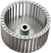
Forward curved blades
Features:
- High power density (frame size about half as large as for wheels with backward curved blades and the same power)
- Impulse wheel → wheel mainly generates kinetic energy, which is converted into static pressure by the case → use only with case
- Total efficiency of 60-65%
- Also called drum impellers → TLR/TS
- Good acoustics
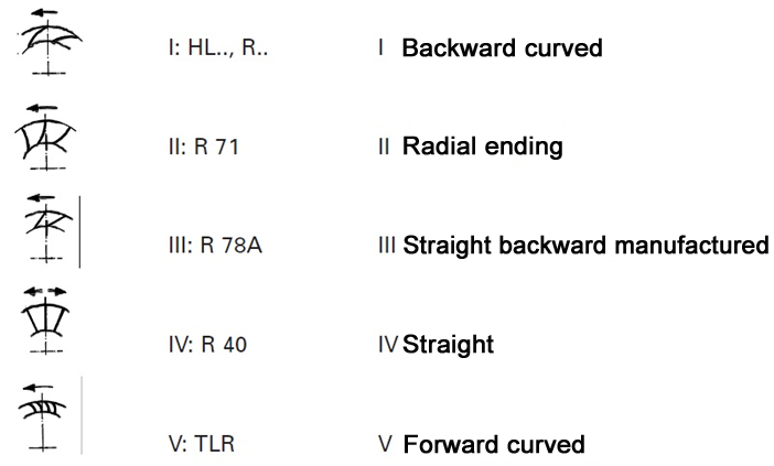
Blade shapes
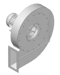
Spiral case
Important parameters
The operating point is calculated from:
- Volume flow
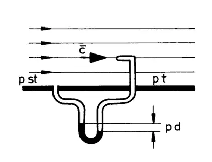
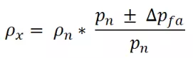
- Static pressure increase Δpfa
- Total pressure increase Δpt
- Air performance (pressure increase x volume flow)
Differentiation of pressure values
Design of fans
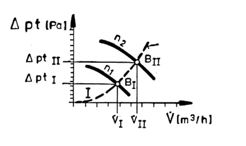
Fan characteristic curve:
- The characteristic curve for pressure in relation to volume flow specifies the volume flow at which a certain pressure increase is achieved.
Plant characteristic curve:
- As a result of the mechanical friction of the plant air, pressure losses occur. As a rule, these increase quadratically with the flow speed → if the volume flow doubles, the pressure loss quadruples. This ratio between the pressure and volume flow gives rise to a parabolic characteristic curve.
Operating point
Note
Ideally, the operating point should be at 50-70% of the maximum volume flow, since in this range, the greatest efficiencies are achieved. If possible, a fan should not work in the leading part of the characteristic curve, which is normally almost horizontal. This is because the volume flow can dive significantly after just a small change in the pressure increase.
Laws of proportionality
Note:
You require a high volume flow but low pressure → large wheel diameter, low speed
You require a low volume flow but high pressure → small wheel diameter, high speed
You have a low medium density (e.g. due to a large height, high temperature, or steam) → the wheel must be designed for a greater pressure increase
If the speed increases by 20% (60 Hz), the power consumption increases by around 75%.
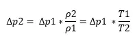
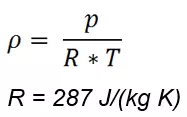
Density change
The change in the density of the conveyed medium must be taken into account when designing fans if:
- Gases with densities other than that of air are conveyed
- Large quantities of steam are in the air
- The medium temperature changes significantly (the density of gases is proportional to the temperature in kelvin)
- The static pressure increase significantly exceeds 3000 Pa (compressibility of air)
- The flow speed exceeds 100 m/s
Note: This applies only if the temperature change can be disregarded.
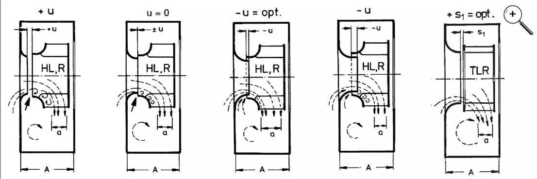
Inlet nozzles
Wheels for dust conveyance
Problem:
On the blade suction side, dust accumulates and is pressed against the blades by centrifugal force. In addition, in this area, the flow speed is lower, so the particles are not blown away. Imbalance can occur.
Solution:
Wheels with straight blades and a low chord angle - so steeper blades - are used. As a result, particles can be better flung out of the wheel by centrifugal force.
Wheel strength
The reliable top speed is determined as follows for impellers:
- The wheel is spun at increasing speed and measured until a lasting deformation of 0.5 mm is achieved. This speed is divided by a safety factor to give the reliable top speed.
- Alternatively: FEM calculation
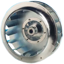
Open radial wheels
Wheels without a cover disk can be used to convey extremely long-stranded media. However, note that such wheels are not suitable for large pressure increases, so they are also called conveyor wheels. In addition, the missing cover disk reduces the wheel strength. Typical applications include air circulators in drying plants.