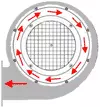
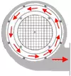
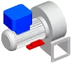
Rotational direction
The rotational direction is defined looking at the suction side of the fan. |
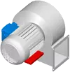
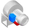
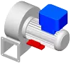
Base, terminal box, and case positions
Important note!
There are 2 types of fan base.
Fan base: For small motor sizes.
In the case of motor sizes smaller than 90 or less than 1.5 kW, the fans generally have an attached base.Motor base: As a rule, for larger motors as of size 90 or a power above 1.5 kW.
The data sheet of the fan indicates whether the fan has a fan base or motor base.
Standard base and terminal box positions for fans with a fan base


Standard base and terminal box positions for fans with a motor base
Standard base and terminal box positions for fans with motor base for ExII2Gc pressure-encapsulated ATEX motors
Standard terminal box positions for fans WITHOUT a base


| If no purchase order specifications are made by the customer, the delivery is as described above. |
| Other positions for the base, terminal box, or condensate holes must be specified by the customer when the order is placed. |
| It is best to use the position configurator for this. |
Position configurator
| View of the suction side | |||
 | |||
| |||
Note
For design reasons, the base position R180 or L180 is not always possible!
Likewise, not all positions are possible for fans with motor base!
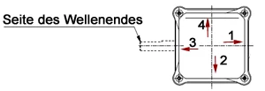
Positions of cable inlets in drive motors
The positions of cable inlets can differ depending on the supplier and motor type. Position 1 or 2 normally applies. If you require a special cable inlet position, please ask us. Please specify the desired position with 1, 2, 3, or 4 as per the drawing.
Note: Motors are generally delivered without cable glands.
Drive motors
All drive motors that are used are designed for continuous operation and meet the applicable VDE regulations, EU directives, standards, and accident prevention regulations.
The following are used as standard:
- 230 V, 50 Hz shaded-pole motors
- 230 V, 50 Hz single-phase alternating current motors with operating capacitor
- 230/400 V, 50 Hz three-phase motors
- 202-306/350-530 V, 50/60 Hz extended voltage range motors
- ATEX motors in the ignition protection classes Ex "e", Ex "d", Ex "de", Ex "nA", or Ex "t"; for the available zones, see our information on the ATEX design.
The shaded-pole motors are designed in insulation class B and IP 20; all others are in insulation class F and IP 54 (to 120 W) or IP 55.
Single-phase motors are available up to a power of 1.1 kW.
Extended voltage range motors are available up to a power of 1.0 kW at 60 Hz.
In the case of three-phase motors as of a power of 5.5 kW, the motor winding is designed for star/delta starting with a voltage of 400/690 V.
Special motors are available on request, for example, special voltages, higher protection classes, with thermal protection devices, in ISO class H, with 60 Hz design, CSA/UL design, and with different shaft dimensions etc.
Temperatures
In the case of standard fans in insulation class F, the permitted temperature of the conveyed medium is -15°C to +80°C, whereby the ambient temperature of the drive motor is not allowed to exceed +40°C.
For the conveyance of hot air/gases, a temperature barrier is used, permitting a conveyed medium temperature of between 250°C and 350°C (higher temperatures available on request).
If integrated variable frequency drives are used, the ambient temperature of +40°C must not be exceeded, since otherwise the electronics are subjected to thermal overload, which can result in significant power losses and failures. In the case of applications with temperatures above 60°C in an Ex-zone, please see our information on the ATEX design.
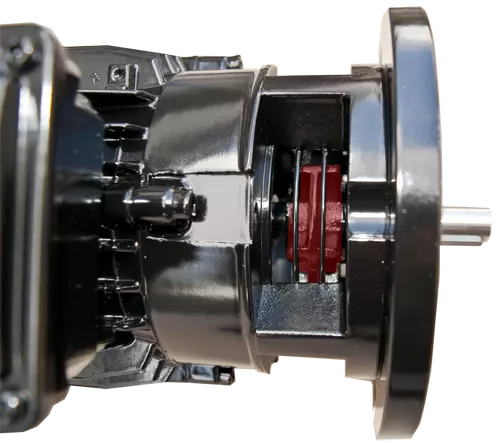
Temperature barrier
Fans for conveying hot gas or air are fitted with a temperature barrier. The temperature barrier is required for non-short-term media temperatures of above 80°C.
For media temperature of more than 250°C
In the case of media temperatures of more than 250°C, the temperature barrier is implemented with spacers between the motor and fan case and a cooling vane. The spacer also includes mechanical touch protection.
For temperatures of -40°C to 300°C
Additional sealing of the shaft feed-through in the fan is realised by means of a flange bell-type motor. Here, the suction side motor flange is open to the fan so that the cooling vane can dissipate the heat. In addition, a radial shaft sealing ring with different sealing materials can be installed at the outer flange end. This enables continuing media temperatures of -40 to + 300°C.
The temperature of the conveyed medium is not allowed to exceed 350°C at a nominal speed of 2,800 rpm and 200°C at 1,400 rpm.
Particular attention must be paid to this, even if operating the fan with a variable frequency drive. In such cases, the use of external motor cooling with a separate drive motor (regardless of the main motor speed) is a possible solution approach, for example.
In the case of non-short-term media temperatures of more than 350°C, thermal insulation is also required for the fan case. The thickness of the insulation depends on the maximum media temperature.
In the case of fans in the APOVENT and APOGUSS range, a temperature barrier is required as of a media temperature of more than 200°C due to other design features of the fan. Here, the temperature barrier takes the form of mechanical touch protection and a cooling vane.
The ambient temperature is not allowed to exceed 40°C for all of these designs. However, if this is unavoidable, a special solution can be offered on a case-by-case basis - depending on all of the applicable conditions.
In the case of increased media temperatures, note that the pressure build-up of the fan decreases in proportion with the density.
Temperature barriers are not available in combination with ATEX fans. ATEX fans are only permitted for atmospheric conditions (media temperature of between -20 and +60°C at the fan inlet).
Fan wheels
All fan wheels used are balanced dynamically on two levels.
The standard balance quality is G6.3 as per DIN ISO 1940 Part 1.
In the case of smaller fans with shaded-pole motors and external rotors, drum impellers with forward curved blades are used; for larger types, high-performance impellers with backward curved blades are used.
For smaller medium-pressure fans, medium-pressure impellers with forward curved blades are used.
Medium-pressure high-performance impellers with backward curved blades are used for larger types.
In the case of fans for the conveyance of dusty media, impeller geometries that prevent the accumulation of dust in the impeller are used.
In general, all fan wheels are available in stainless steel (1.4301). On request, they are also available in 1.4404 and 1.4571
Transport fans contain open impellers with backward curved blades and sometimes radial ending blade tips. In each case, the wheel has no cover disk.
High-pressure fans have slim impellers with heavily backward curved blades. These impellers are often made from aluminium.
Detailed information on fan wheels and the design of fans
Alles was Sie über Ventilatorräder wissen sollten
Terms, symbols, and units
| V° | Volume flow [m³/h] or [m³/min] |
| Δpfa | Static pressure difference [Pa] |
| Δpt | Total pressure difference [Pa] |
| U | Voltage [V] |
| I | Rated current [A] or [mA] |
| Pel(auf) | Power consumption of fan [W] or [kW] |
| Pw(ab) | Rated power of motor [W] or [kW] |
| Lp | Sound pressure level [dB(A)] |
| n | Speed [rpm] |
Pressure conversion table
| Pa | daPa | mbar=hPa | kPa | mm Ws |
| 1 | 0,1 | 0,01 | 0,001 | 0,1 |
| 10 | 1 | 0,1 | 0,01 | 1 |
| 100 | 10 | 1 | 0,1 | 10 |
| 1000 | 100 | 10 | 1 | 100 |
The noise that occurs when a fan is in use is caused by whirling and turbulence in the flow processes in the impeller and case and by tonal components (fundamental tone of rotation - the product of the number of blades and the rotary frequency). In addition, secondary noises can arise due to mechanical vibrations. However, these can be largely avoided by appropriate design measures and a high impeller balancing quality.
Among other things, the installation situation, the differing spatial conditions that occur in practice, and the operating point of the fan are important parameters for the noise emission values.
The sound pressure levels were measured in dB(A), for installation type:
(see characteristic curve measurement procedure) on the air outlet at a distance of 1 m and below 45 degrees. The specifications on the sound pressure level on the individual data sheets relate to the approximate optimum operating point of the fan (with around 60% of the volume flow).
Characteristic curve measurement procedure
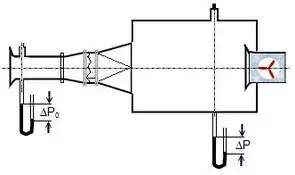
The fan characteristic curves depicted in this catalogue were determined in accordance with DIN 24163, test bench arrangement 1, installation type A, in a test chamber (free air intake and delivery).
Kennlinien – Messverfahren Bilder
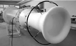
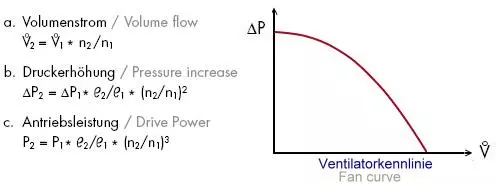
Fan characteristic curve
In the characteristic curves determined in the test chamber as per Fig. 1, the relationship between the static/total pressure increase and the volume flow is displayed. These are standard characteristic curves, which means that they apply only for the defined suction-side and pressure-side connection conditions, which are actually rarely found in practical usage, meaning that deviations from the relevant standard characteristic curve are to be expected. The measurement results depicted in the standard characteristic curves are converted to an air density of 1.205 kg/m3 at a temperature of 20°C and an air pressure of 1013 mbar.
The laws of similarity mechanics apply for the conversion of the measurement results to other densities and speeds.
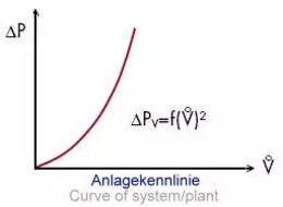
Plant characteristic curve
The plant characteristic curve displays pressure loss that occurs in the plant depending on the volume flow due to friction, displacement whirling, and speed changes etc. In the case of flow-through plants, it is normally a parabola with the exponent 2, usually running through zero.
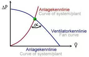
Operating point
The operating point of a fan is where the fan characteristic curve intersects with the plant characteristic curve. It is important to strive for a stable operating point (the two characteristic curves only intersect once with a sufficiently large angle) that should lie at around 60% of the achievable volume flow (optimum operating point).
Fan selection
In principle, Karl Klein radial fans are designed for use over the entire characteristic curve range, so from fully throttled (V° = 0 m3/h) to free-blowing (V° max.), whereby the most efficient working range is between 15% and 85%.
The correct choice of fan is made on the basis of the required conveying power (volume flow) and the desired pressure difference. The available space and generated operating noise as well as any chemical and thermal requirements are naturally also important.
Pressure loss calculator
Important data for inquiries
- Operating point (intersection of volume flow and static pressure)
- Voltage
- Frequency
- Flow type
- Temperature of conveyed medium
- Type of conveyed medium
- Speed and terminal box position
- Accessories and special requirements